Simulation of Flow Over NACA 0015 Airfoil
Omar Husain, 27 April 2019
For my computational Fluid Dynamics class the final project was to solve a set of partial differential equations (equations that depend and change with respect to several variables) for some physical problem using a computer model. I chose to model the flow over a symmetric airfoil (airplane wing) at supersonic speeds (i.e. at speeds many times over the speed of sound.)

NACA 0015 Airfoil Shape
In the future, as airplane technology continues to be developped, these types of speeds will be possible and so it is important to model this flow. At a mach speed of 10 (10x the speed of sound) a flight between Montreal and Paris would take less than half an hour.
The model for this simulation is based on the Compressible Euler Equations, which are balance laws based on mass, momentum, and energy conservation for inviscid (no viscosity) flow.

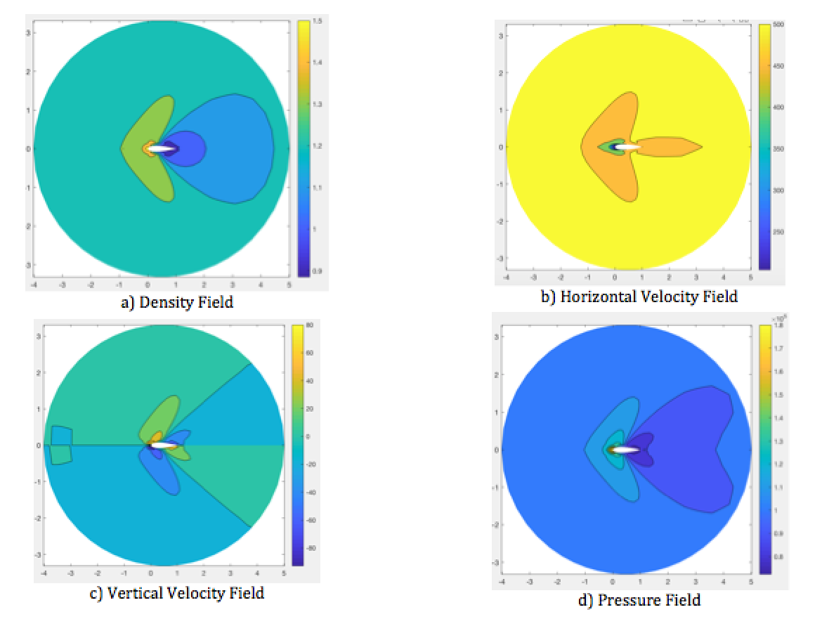
Flow Characteristics at Angle of Attack of 0 deg
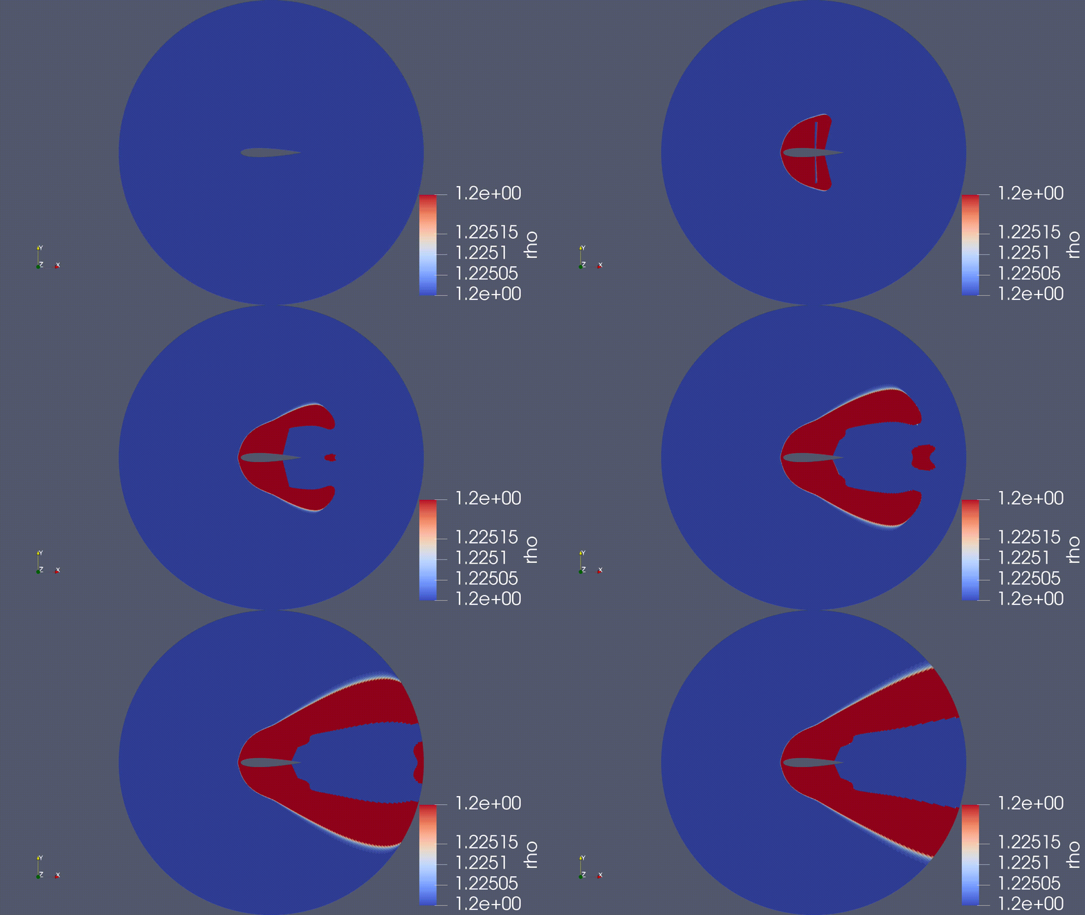
To create the computational model, the cross-sectional shape of the airfoil has to be determined and the space around it has to be divided up into little cells. In each of these little cells, the physics of the flow will be solved. The computer model is told to run for a given amount of time and computes the physics of the flow at a discrete number of time steps. This allows us to show an animation of how the flow develops in time.

At mach speeds greater than 1 (faster than the speed of sound) shock waves are introduced. These shock waves are small areas where the properties of the flow jump drastically to different values. The flow substantially decreases in velocity after the shock wave and increases in pressure, as can be seen in the animation. In the animation above, the shock wave is the thin white contour over which the pressure field changes from blue to red.
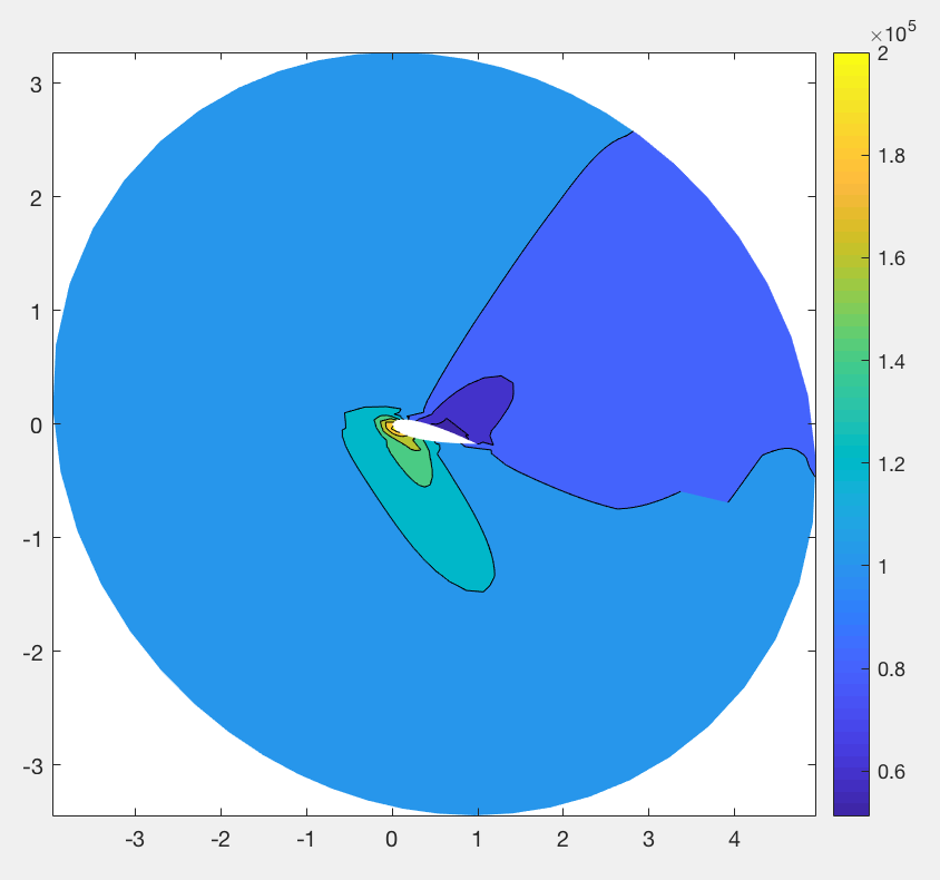
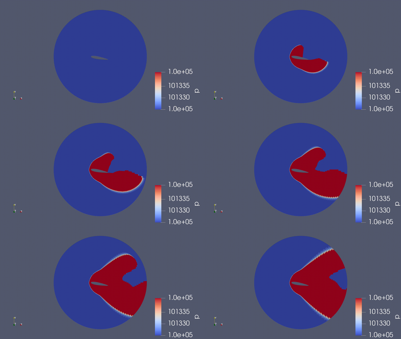
The lift produced by an airfoil is based on the pressure difference from the top surface and the bottom surface. If the airfoil is tilted upwards, the pressure on the bottom surface is greater than the pressure on the top surface and the airfoil produces lift.

Airfoil at an Angle of Attack of 10 degrees
In this image, the white part in the middle is the airfoil and the colour map gives an indication of the pressure field of the flow around the airfoil. The following animation shows how the pressure develops when the airfoil has an angle of attack greater than zero (when the wing is tilted upwards).

This project was initially developed in Matlab, but I wanted to have a higher resolution so I wrote it in C++ with some of the functions already given by my professor.