Gear Box - Mechanical Design
Omar Husain, 31 March 2019
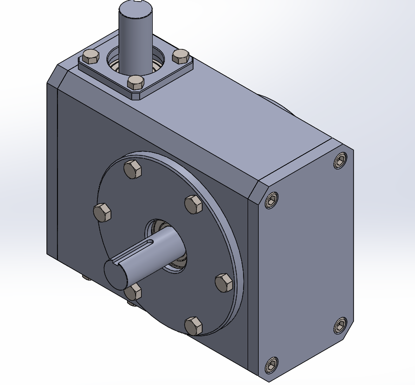
Gear Box CAD Model
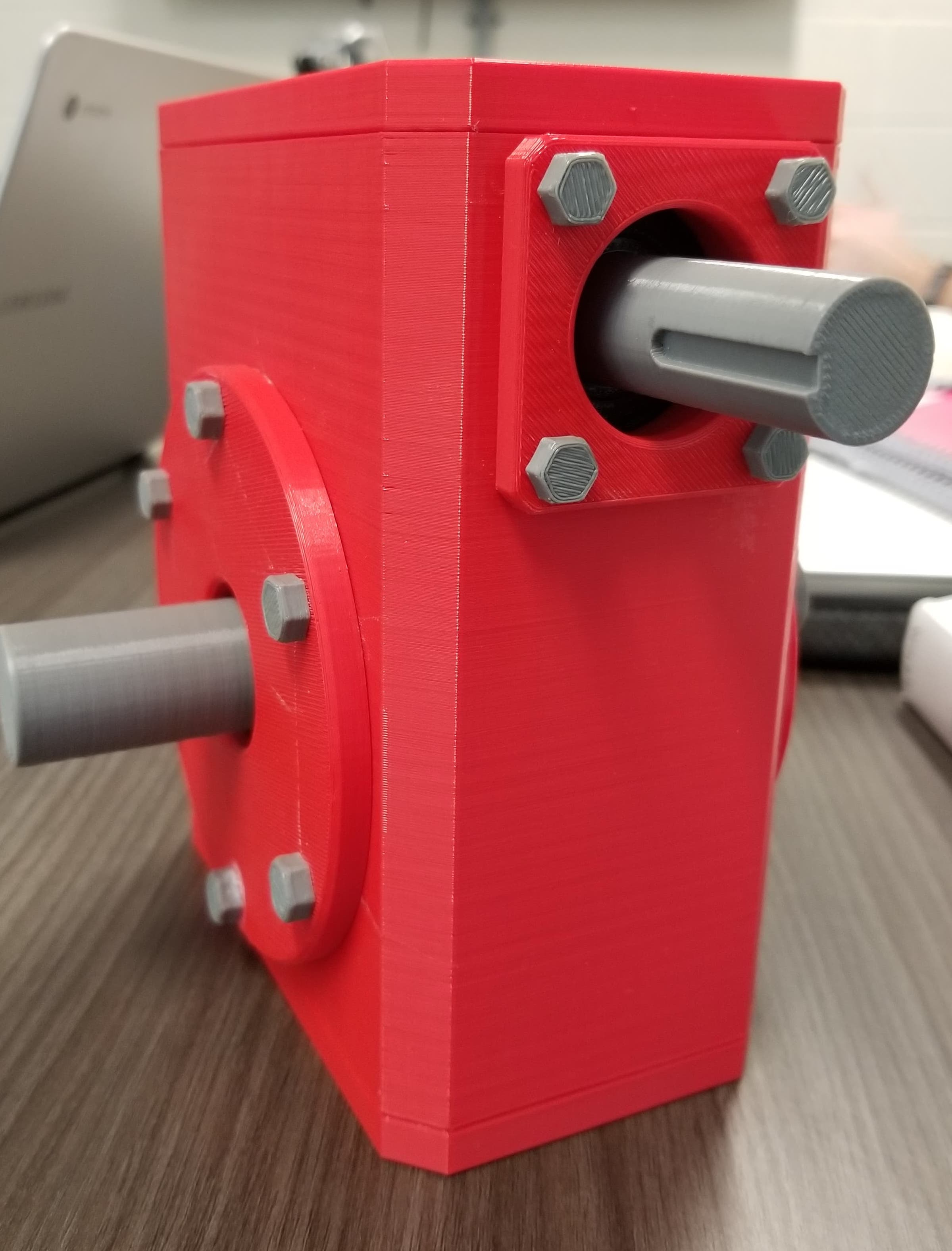
3D Print of the Gearbox
This gearbox design was a group project with Dave Clarke and Humam Shwaikh at the University of Ottawa. Dave Clarke created the beautiful computer aided design (CAD) model above.
The task for this project was to design a speed reducer/gearbox given certain operational requirements. A gearbox is a means of transmitting the rotational power of a motor from one location to another with possibly varying speeds and torques.
The focus was on making a simple, cheap, and compact gearbox. A full analysis of the stresses on the gears, bearings and shafts was conducted, in order to design a gear box that met the given criteria.
The following table shows the criteria given for this particular gear box.
| Design Constraint | Input Power (HP) | Input Velocity (rpm) | Output Velocity (rpm) |
|---|---|---|---|
| Vertical to horizontal | 5 | 750 | 80 |
This corresponds to a speed reduction of 9.375. This is a relatively high reduction, so to achieve it in one step a worm gear was used with a triple thread and a wheel with 29 teeth. This corresponds to a speed reduction of 9.67, which is very close to our design requirement. A worm gear also transmits the rotation from a vertical to horizontal shaft, which meets our design constraint.
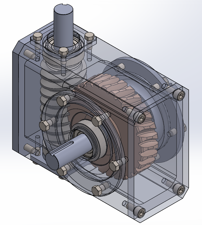
Gearbox Final Design
My principal task was to analyse the shafts in this gear box. The worm gear generates axial, transverse and radial forces on the shafts. The shafts can be modeled as simply supported beams with a center load. This means that a large bending moment is generated within the shaft at the center and has the following profile.
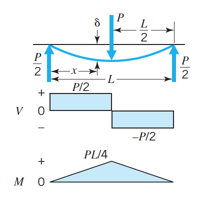
Shear and Bending Moment Diagrams of Shaft
The length of the shaft is set by the gear analysis and the bearing analysis. The shaft length is minimized in order to maintain a compact volume and to reduce the bending moments in the shaft. The design parameter of the shaft is therefore the diameter.
Since a gear box is subject to repeated cycles, the main mode of failure to be expected is fatigue. The modified Goodman criterion is used to determine the shaft diameter that will prevent fatigue failure. This criterion considers the mean and alternating principal stresses induced in the shaft and the material properties of the material selected in order to determine the diameter of the shaft at key locations.
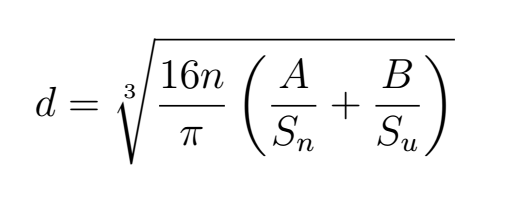
Modified Goodman Criterion
The main requirement is that the tortional deflection or angle of twist of the shaft not exceed 0.08 °/ft. By increasing the diameter of the shaft the moment of inertia is increased, which increases the resistance to twisting induced by the tortional loads on the shaft. Basically, having a chubbier shaft prevents the shaft from twisting too much and ultimately failing.