Self-Leveling Glider - Controls Project
Omar Husain, 01 November 2017
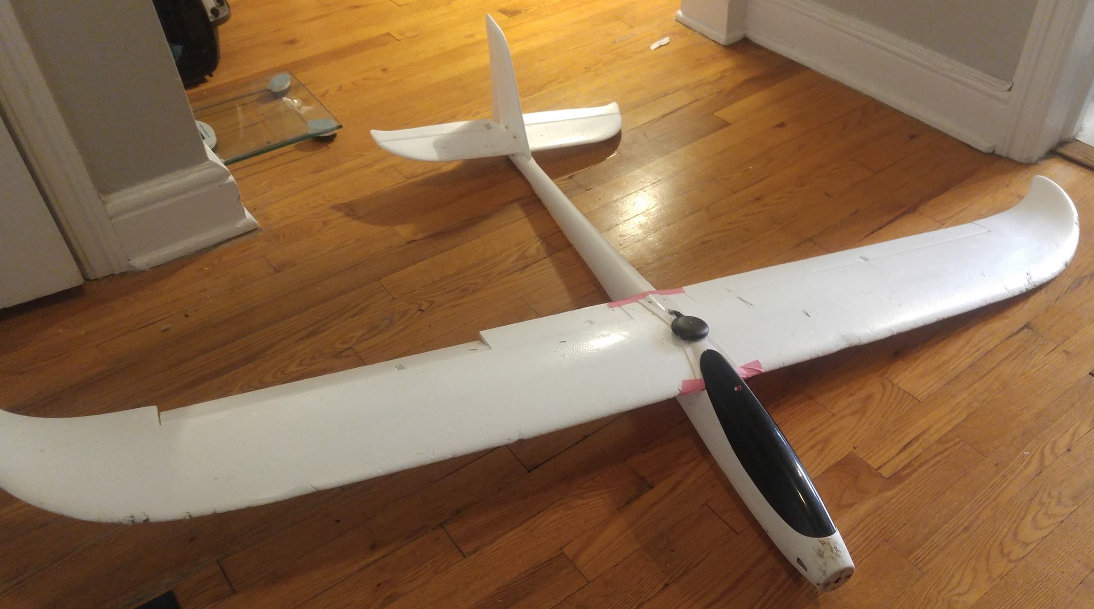
The motivation for this project was to design a control system for a glider that would allow it to correct it’s orientation and fly straight and level given any starting angle and any external disturbances.
The system consists of a lipo battery, an inertial measuring unit (IMU), a PID controller, and three servo motors to actuate the control flaps.
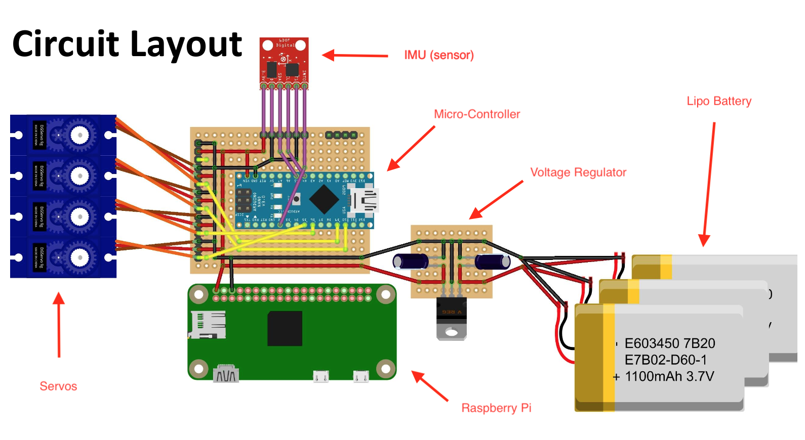
This project presented both software and electrical design decisions. In order to power all three servos and the micro-controller, a 12V 1.5A lipo battery was chosen. Each servo is rated at 5V; therefore, a voltage regulator was used to step down the voltage to a constant 5V across each servo. In addition, a raspberry Pi was connected to the circuit in order to feed data from the controller and store it to be able to theoretically assign gain values to our controller in Matlab. The full circuit is shown in Fig. 1.
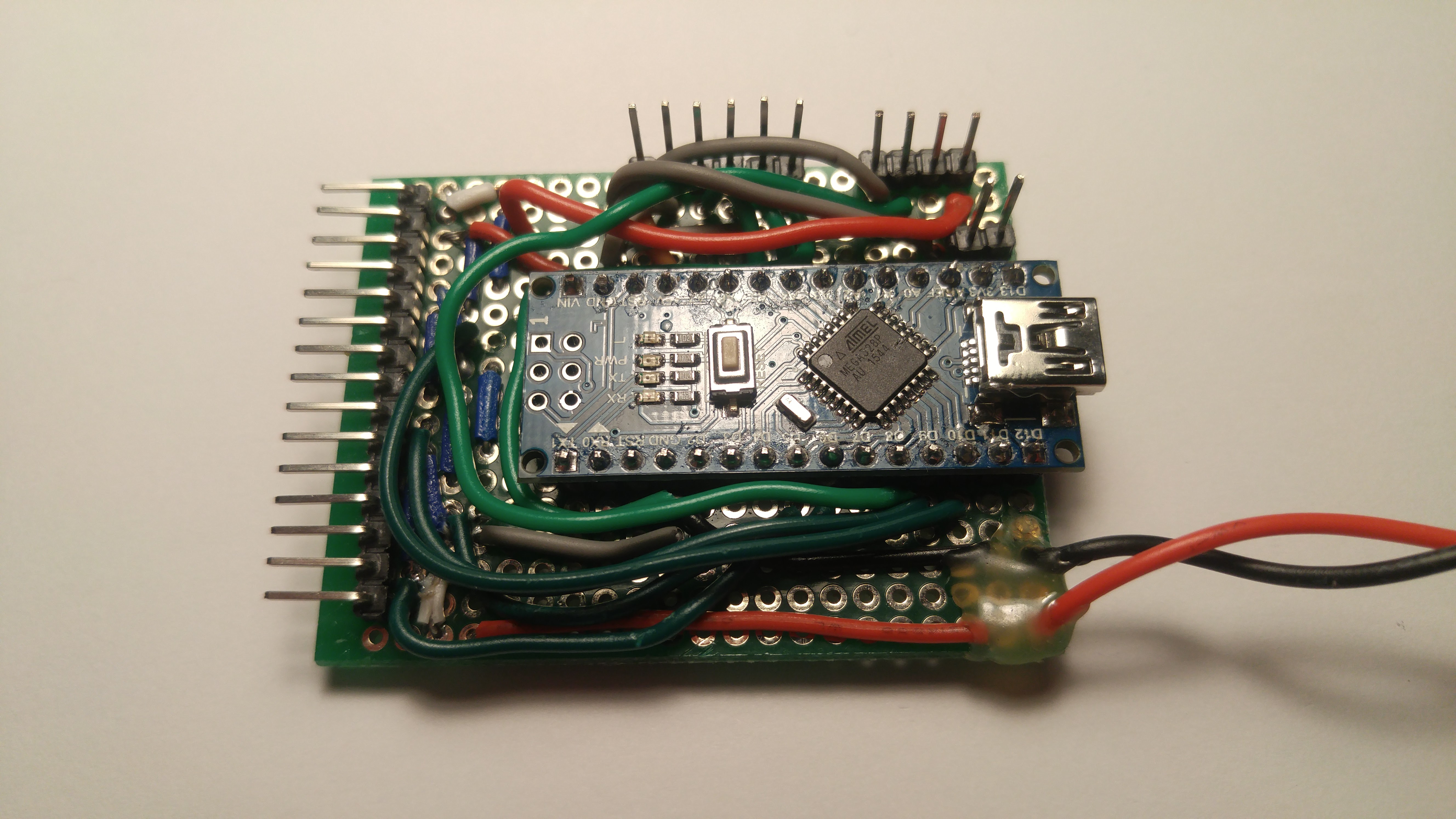
With the electronics sorted, the next step was to code the controller. An arduino nano was used with an IMU that had a nicely documented arduino library. The IMU fed raw data from an accelerometer and gyroscope, which had to be transformed into values for the roll, pitch, and yaw orientation of the glider. A complicated mathematical transformation known as a Quaternion was used to map the raw sensor output into useable orientation data. With this transformed data, the PID controller calculated the deviation from the desired orientation of straight and level. The output of the controller was a command for the servos attached to the rudder, ailerons, and elevator of the glider and the feedback system cycled through again.
Finally, the PID controller needed to be tuned, or given the proper gain values, in order for the system to be stable. At first, the goal was to theoretically determine the gain values by taking the transformed data from the controller to the Raspberry Pi and then running it through a Matlab PID tuning function. This function tries to determine the transfer function given some data and then provides gain values based on a step response of the system as shown in Fig. 3.
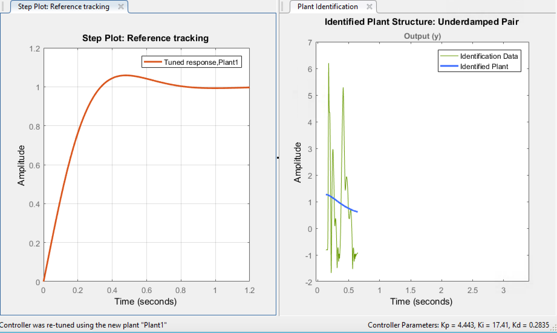
However, theory does not always match reality. So the gains were initially set to these values shown above, but this produced poor results. The PID gains were instead tuned experimentally, by changing each gain individually by small increments until the desired result was obtained. You can see the final results on youtube: